|
|
|
Kategorie
|
|
Informacje
|
|
Polecamy
|
|
|
 |
|
|
Dla tego produktu nie napisano jeszcze recenzji!
 ;
Schematy są ale można wysilić się i zrobić kolorowy skan i o większej rozdzielczości. Wtedy schematy płytek będą czytelniejsze. Całość super jako wartość merytoryczna. Wszystkie dane potrzebne do podłączenia różnego rodzajów urządzeń takich gramofon, CD itd.
 ;
Szybko, sprawnie i tanio. Serwis godny polecenia. Będę polecał innym
;
Ogólnie jest OK, z wyjątkiem obrazu płyty głównej, który jest miejscami mało czytelny, ale można sobie poradzić.
;
Dokładna dokumentacja, pomogła w szybkiej naprawie telewizora. Dziękuję!
;
jedyne do czego mogę mieć zastrzeżenie to jakość zdjęć zawartych w przesłanej instrukcji serwisowej ponieważ są fatalnej jakości, praktycznie nieczytelne. tak poza tym jestem zadowolony to jest to czego szukałem.
Model 140A
Section IV Paragraphs 4-18 to 4-25
t RECTIFIER
DOUBLER
4
HIGH VOLTAGE
TRANSFORMER
I
-RECTIFIER V304
I
REGULATOR v301I0301
1-1
w
i
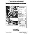
Figure 4-3. High-Voltage Power Supply Block Diagram
the transistor is off. Brea :downdiode CR202 reduces the output impedance, and provides temperature compensation for the circuit. Voltage divider R207/ R208 reduces the 10-volt output to 1 volt. Both 10volt and 1-volt outputs a r e available on the front panel of the Model 140A.
4-18. HIGH-VOLTAGE POWER SUPPLY.
4-19. Figure 4-3 is a block diagram of the high voltage power supply. The output of a regulated transistor oscillator is stepped up in voltage and applied to a s e r i e s of high-voltage rectifiers. The positive output of the voltage doubler is connected to the post-accelerator of the CRT. The negative outof the CRT put voltages a r e used in the gun assembly and its associated controls. The Z - A X I S INPUT can be used to apply an intensity modulating signal to the cathode of the CRT. 4-20. Figure 5-8 is schematic diagram of the highvoltage power supply, including the CRT. Oscillator Q302 operates at a frequency of about 32 kc. Any change in the output voltage is applied to the grid of V301, which converts the voltage change to a current change. This current change is applied by emitter follower Q301 to the base of the oscillator transistor. The amplitude of oscillations is changed in such direction a s to oppose the original output voltage change. High Voltage Adjust R319 s e t s the amplitude of oscillation to produce the correct output voltage.
4-22. Two separate negative supr ies a r e usel , one for the control grid o f t h e CRT,- and one to provide CRT cathode and focusing voltages. Both supplies use half-wave rectifiers (V304 and V305). The unblanking gate from the horizontal plug-ins (via pin 1, J 2 ) is applied to the return side of the grid supply, and changes the negative grid voltage by about +50 volts to unblank the trace. A positive pulse of about 20 volts will blank the trace when applied to Z-AXIS INPUT. When Z-AXIS INPUT is not used, S301 is set to INT to receive chopped blanking from a dualtrace plug-in. 4-22. The voltage doubler circuit (V302/V303) provides the 5-kc post-accelerating voltage required by the CRT. 4-23. The ASTIGMATISM adjustment (R341) affects the roundness of the spot, and the Geometry adjustment (R343) is used to optimize pattern shape.
a
4-24. TRACE ALIGN.
4-25. Trace-aligning coil L302 is located around the CRT near its screen. Adjustment of Trace Align R350A/B varies the magnitude and direction of current through the coil, which has the effect of rotating the trace. In this way the trace is brought into alignment with the CRT graticule.
01638- 1
4-3
|
|
|
> |
|